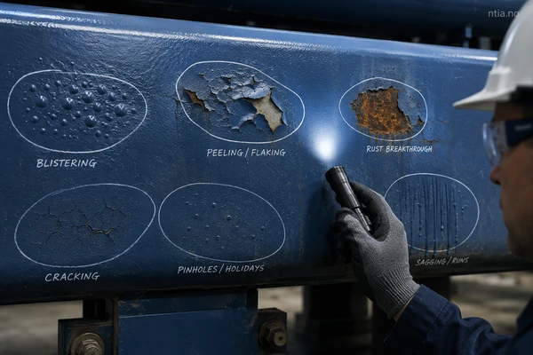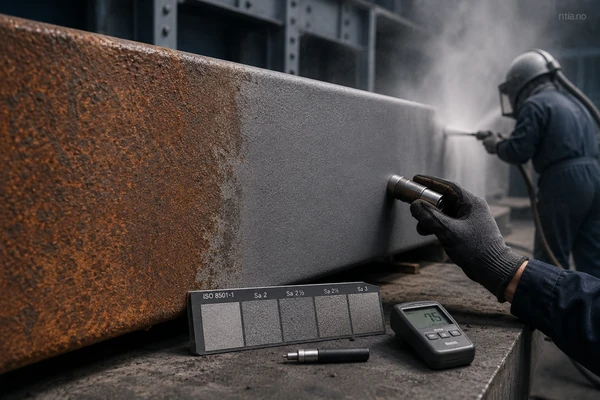
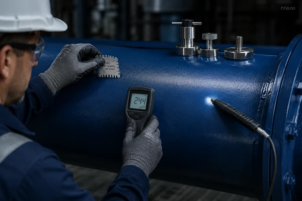
WFT, DFT, holiday and adhesion tests do not provide four versions of the same answer. They address different questions at different stages of coating work: how much wet material is being applied, how thick the dry film is, whether the film has through-coating discontinuities, and how the coating responds to a specified adhesion method.
The practical task is to select the right test, control the instrument and conditions, interpret only what the method can prove, and record enough evidence for another reviewer to reconstruct the decision. This article focuses on that logic. For the wider before-during-after inspection sequence, use NTIA’s coating inspection guide.
Choose the test by the inspection question, not by the instrument that happens to be available. The four methods can support one inspection plan, but none of them substitutes for the others.
| Test | Typical stage | Question answered | Primary output | Does not prove |
|---|---|---|---|---|
| WFT | During application | Is the wet film being deposited at a level likely to achieve the intended DFT? | Wet-film reading and process-control adjustment | Final DFT conformance |
| DFT | After the specified dry/cure state | Does the measured dry-film thickness conform to the specified rule? | Readings evaluated against a defined sampling/conformance basis | Continuity, adhesion or service life |
| Holiday | After sufficient cure and required thickness checks | Are there detectable through-film discontinuities? | Holiday locations, repair and retest status | General DFT or adhesion |
| Adhesion | After cure, qualification or when otherwise specified | How does the coating respond under the specified adhesion method? | Pull-off value/failure mode or cross-cut/tape classification | Interchangeable strength values or whole-surface performance |
| METHOD BOUNDARY Use each result only for the question its method is designed to answer. A collection of readings does not become evidence of overall coating quality unless the governing documents define how those readings support acceptance. |
Wet film thickness (WFT) is measured while the coating is still wet. ASTM D4414-25 describes measurement of wet-film thickness by notch gauges and characterizes the result as approximate. Its main value is immediate process control: the applicator can identify an under- or over-applied wet film before the coating has fully dried.
A notch gauge should be used at the time and in the manner defined by the approved procedure and coating documentation. Delay can matter, particularly with fast-drying products or surfaces where the gauge cannot make representative contact. The location should also be chosen so the reading reflects the applied film rather than an edge, weld, irregularity or unsuitable geometry.
An indicative relationship can be written as:
| INDICATIVE RELATIONSHIP WFT = target DFT ÷ applied volume-solids fraction |
The critical word is applied. The volume-solids value is normally based on the product as supplied, while field thinning can change the effective solids fraction. Manufacturer guidance such as Hempel’s mixing and thinning technical guidance explains why the thinning basis must be included when estimating WFT.
Example scenario: if an approved coating procedure uses a target DFT of 100 µm and an applied volume-solids fraction of 0.80, the indicative WFT is 125 µm. This is a calculation example, not a universal acceptance value. The actual target, allowable range, thinning allowance and measurement practice must come from the approved project and product documents.
Do not convert one convenient WFT reading into a final thickness acceptance statement. The film still needs the specified DFT verification after it reaches the required dry or cure state.
Dry film thickness (DFT) is the thickness of the coating after it has reached the state specified for measurement. ASTM D7091-22 covers nondestructive use of magnetic and eddy-current gauges on metal substrates and distinguishes calibration, verification and adjustment. It also makes clear that the standard supplements—not replaces—the instrument manufacturer’s instructions.
A single displayed value is not yet a conformance decision. The inspector needs the correct gauge principle for the substrate, a valid instrument-control process, a defined measurement area and location plan, raw readings, and the applicable rule for evaluating those readings.
AMPP SSPC-PA 2-2022 addresses a procedure for determining conformance to a specified DFT range on ferrous and non-ferrous metals. ISO 19840:2012 provides a verification procedure for DFT on rough surfaces. ISO 2808:2019 covers a broader range of paint-film thickness methods. The project must identify which method, edition, sampling plan and conformance rule apply.
This separation prevents a common error: using a gauge correctly but evaluating the readings against an invented average, an internet summary or a rule from another project. Measurement answers what the gauge detected. Conformance answers how the approved specification tells the inspector to judge the data.
DFT does not prove that the coating is holiday-free or adequately adhered. A coating can be within its thickness requirement and still contain a pinhole, mechanical damage, contamination-related weakness or another defect outside the scope of the DFT method.
Holiday testing is used to detect discontinuities in a nonconductive protective coating or lining over a conductive substrate. The current official AMPP/NACE SP0188-2024 record covers both high- and low-voltage holiday detection for new protective coatings and linings. The applicable method depends on the coating system, substrate, film condition, project requirement and referenced procedure.
Low-voltage wet-sponge and high-voltage methods are not interchangeable defaults. The inspector should not select a method from coating thickness alone unless the governing standard and coating-system documentation use that basis. Surface moisture, contamination, inadequate cure, poor grounding, electrode condition, travel rate and access can all affect the result.
The official ASTM page currently labels ASTM D5162-21 as Historical. It may still be contractually applicable where a project explicitly invokes that edition, but it should not be presented as the current general recommendation. ASTM G62-23 remains an active method for holiday detection in pipeline coatings; its pipeline scope should not be generalized to every coating system.
| STANDARD WATCH Record the exact standard and edition named by the project. If the documents cite a historical, withdrawn or conflicting reference, raise a controlled clarification rather than silently substituting a newer document. |
An incorrect test setup can miss discontinuities or damage the coating. For that reason, this article does not provide a universal test voltage, thickness threshold or travel rate. Those parameters must be taken from the applicable standard, project procedure and coating manufacturer’s approved guidance.
Adhesion testing is method-dependent. A pull-off value and a cross-cut or tape classification are different outputs produced by different stress mechanisms; they should not be converted into one another or compared as if they measure the same property.
ASTM D4541-22 covers pull-off strength of coatings on metal substrates using portable adhesion testers. The official summary identifies several variables that can affect results, including the adhesive, loading fixture, cure, pull rate, environment, scoring and instrument. ISO 4624:2023 specifies three pull-off test methods and emphasizes method and substrate context.
The reported number is only part of the result. The inspector should record where separation occurred: within a coating layer, at an interface, within the adhesive used to attach the fixture, or as a mixed failure. A high displayed value with glue failure may say more about the test assembly than the coating/substrate interface being investigated.
ASTM D3359-23 describes tape-test methods for rating adhesion and notes that they do not produce an absolute rupture force or make fine distinctions at higher adhesion levels. ISO 2409:2020 covers a cross-cut method for assessing resistance to separation. These methods provide classifications within their own procedures, not tensile pull-off strength.
Operator technique, cutting tool condition, spacing, film thickness, substrate, tape and timing can influence the result. The applicable method must therefore be specified before testing. A result from one device, standard or procedure should not be compared with another without a documented technical basis.
Instrument control must be described precisely. Calling every check “calibration” hides who performed it, what reference was used and whether the gauge was adjusted in the field.
| Control | Practical meaning | Inspector evidence |
|---|---|---|
| Calibration | A controlled comparison establishing the instrument’s measurement relationship, normally performed by the manufacturer or a qualified laboratory. | Certificate/status, instrument ID, date and validity as required by the quality system. |
| Verification | A check that the instrument reads within the permitted tolerance on a known reference or suitable base before and during use. | Reference used, readings, time/frequency and acceptance. |
| Adjustment | A permitted change to the instrument response so it reads correctly for the measurement condition. | Adjustment basis, substrate/reference, resulting check and responsible person. |
| Environmental/method conditions | Conditions that can affect the coating, instrument or test response. | Temperature, moisture, cure, cleanliness, geometry or other method-specific conditions required by the procedure. |
The exact definitions and permitted actions must follow the selected standard and instrument instructions. The key audit question is simple: could another competent person see what was checked, with what reference, when, and whether the instrument was acceptable before the reported measurements were taken?
A test method explains how to obtain or classify a result. It does not always supply the project’s acceptance value, frequency or disposition rule. Before testing, identify the document hierarchy established by the contract and quality plan.
If documents conflict, do not choose the most convenient value or the newest edition found online. Record the conflict and obtain a controlled decision from the responsible authority. The resolution should be available to the applicator, inspector and reviewer before acceptance is signed.
This matrix connects each test to the decision it can support. It is not a substitute for the project procedure; it is a control against asking one method to prove something outside its scope.
| Test | Decision supported | Key dependency | Minimum evidence | Explicit limitation |
|---|---|---|---|---|
| WFT | Application is being controlled toward the intended dry-film build. | Applied volume solids, thinning, timing, gauge contact and location. | Area/coat, gauge, individual readings, applied-solids basis and process adjustment. | Not final DFT acceptance. |
| DFT | Measured dry-film thickness conforms to the specified evaluation rule. | Substrate, gauge principle, verification, sampling and project rule. | Raw readings, locations, instrument/reference checks, calculations and disposition. | Does not prove continuity or adhesion. |
| Holiday | The specified area has been checked for detectable through-film discontinuities. | System/substrate applicability, cure, method, voltage basis, grounding and coverage. | Standard/method, voltage, electrode, coverage, holiday locations, repair and retest. | Does not measure general DFT or adhesion. |
| Adhesion | Coating response is classified under the specified adhesion method. | Method, substrate, cure, fixture/adhesive or cut/tape controls and operator technique. | Value/classification, method parameters, failure mode, location, repair and disposition. | Methods are not interchangeable; a spot test does not guarantee the whole surface. |
Knowing the test names is different from selecting, controlling and documenting them in practice. NTIA’s Industrial Coating and Painting Inspector Training Course covers coating application, inspection, quality control, testing and performance evaluation within a structured learning path.
A useful record allows a reviewer to reconstruct what was tested, where, under which requirement, with which instrument, what the raw result was and how the final disposition was reached. “Test passed” is not enough.
NTIA’s inspection evidence and recordkeeping guide provides the broader documentation context: records should identify what was inspected, where it was inspected, which method was used and what result was obtained, together with instrument and corrective-action evidence where applicable.
| Error | Why it creates risk | Required action |
|---|---|---|
| Accepting DFT from WFT prediction | Applied solids, thinning, evaporation and application variability can change the final film. | Use WFT for process control and perform the specified DFT verification. |
| Reporting only averages | Local readings and the sampling rule cannot be reconstructed. | Retain raw readings, locations and the conformance calculation. |
| Calling every instrument check calibration | The record hides verification and adjustment activity. | Use the terminology of the applicable method and instrument instructions. |
| Copying a holiday-test voltage from a generic table | The method may be unsuitable or may damage the coating. | Use the applicable standard, procedure and coating-system guidance. |
| Using historical D5162 as a current general reference | The official ASTM status is Historical. | Use it only when contractually invoked and document the edition/status issue. |
| Recording an adhesion number without failure mode | The result may reflect glue, fixture or another interface rather than the intended bond. | Record the failure plane and required method parameters. |
| Comparing cross-cut and pull-off results directly | They use different procedures, stress mechanisms and outputs. | Interpret each result only within its governing method. |
| Leaving destructive test locations open | The inspection itself can create a coating discontinuity. | Repair, cure as required, retest where specified and close the disposition. |
WFT is measured while the coating is wet and is mainly used to control application. DFT is measured after the specified dry or cure state and is evaluated against the project’s thickness-conformance rule.
WFT normally supports process control rather than final dry-film acceptance. The project documents govern, but an indicative WFT prediction does not replace the specified DFT measurement.
That depends on the project. ASTM D7091 addresses gauge use, while documents such as AMPP SSPC-PA 2 or ISO 19840 can provide conformance procedures within their scopes. The specification must identify the applicable method, edition and rule.
Use the method required for the coating system, conductive substrate, film condition and project procedure. Do not choose solely from a generic thickness threshold or voltage table.
No. Holiday testing looks for detectable through-film discontinuities; DFT measurement evaluates film thickness. A coating may pass one test and fail the other.
Pull-off testing applies tensile force through a bonded fixture and reports a value with a failure mode. Cross-cut or tape methods classify coating separation around a defined cut pattern. The outputs are not interchangeable.
Record the observed separation plane using the terminology required by the governing method—for example, cohesive failure within a layer, adhesive failure at an interface, glue failure or a mixed failure.
Include traceable location and coating details, governing documents, conditions, instrument control, raw results, evaluation rule, acceptance status, repair or retest, final disposition and sign-off.
Before any coating test, write down the exact question the result is expected to answer. Then confirm the applicable method, edition, instrument controls, conditions, sampling plan, acceptance source and evidence fields before the first reading is taken.
For the complete inspection sequence, return to the coating inspection guide. For structured learning in coating application, inspection, testing and QA/QC documentation, see the Industrial Coating and Painting Inspector Training Course.

At NTIA (Norwegian Technical Inspection Academy), we specialize in delivering world-class training programs in vendor inspection, quality surveillance, and technical compliance – specifically tailored for professionals in the oil, gas, and energy industries.
Copyright © 2025 by NTIA. All Rights Reserved.